 Ordered all the foundational materials needed to cover the tail and wings. Not included in the screen cap at left is 30 feet of aluminum trailing edge (in 5' strips) and a quart of 3M Fastbond 30-NF water-based contact cement... the same blue-green stuff supplied to Stewart Systems who rebrands it as Ecobond and sells it for $15 more. All but the cement is coming from Aircraft Spruce. December 10, 2019 Because this plane has been flying safely and efficiently for four years now, I am more comfortable sharing the plans I've drawn up for this wing. No other file formats will be provided. You must convert as needed on your own. I DISCLAIM ANY AND ALL FORMS OF LIABILITY FOR HOW THEY ARE USED. Wing Plan Drawing 43012_Wing_Plan.pdf New Root LE Bracket Design Plans Weedhopper_NewLE_RootBracket.pdf Rib Outlines 43012_CutLayout_Plywood2_Ribs.eps Rib Webbing Cutouts 43012_CutLayout_Plywood2_Cutouts.eps |
 September 30, 2014:
This is what my original wing trailing edge (TE) spars look like, a mismash of fixes on the ends to repair wallowed holes. The central outer reinforcement sleeve came with the plane when I bought it in 2001. It actually had a second sleeve over top of it that I removed in 2008 as part of my "Lighten The Bird" rebuild. Due to all of the above, I'm remaking the TEs. |

 Construction begins with four, 7-foot lengths of 1.5" OD x 0.058" wall 6061 T6 aluminum tubes, a 16" length of 1.375" OD tube (058 or 065, whatever I had on hand), and a box of 1/8" dia x 1/8" grip aluminum pop rivets. I measured out the spacing of four rows of rivets, 90 degrees apart, then drilled one hole through both the TE and its inner sleeve splice and popped a rivet to hold it in place. I then drilled the remaining 17 holes (5 rivets in rows 1 and 3 and four in rows 2 and 4). |
 With the splice securely attached to each half of the TE tube, the other halves were slipped on, aligned, drilled, and riveted. |

 October 24, 2014: Now begins the thrust/drag and compression strut rigging, but somehow I overlooked ordering saddle washers for 1.5" OD tube, which provide a wobble-free base. Not to worry, Scott McClure to the rescue with a rush order of 18 pieces, which arrived in two days via USPS mail (Thanks Scott!). The brackets shown are made from 1 1/4" x 1/8" 6063 T52 aluminum C-channel (1" ID) and are attached to the wing TE and LE spars with 3/16" x 1/4" grip aluminum pop rivets. |


| March 25, 2015: |
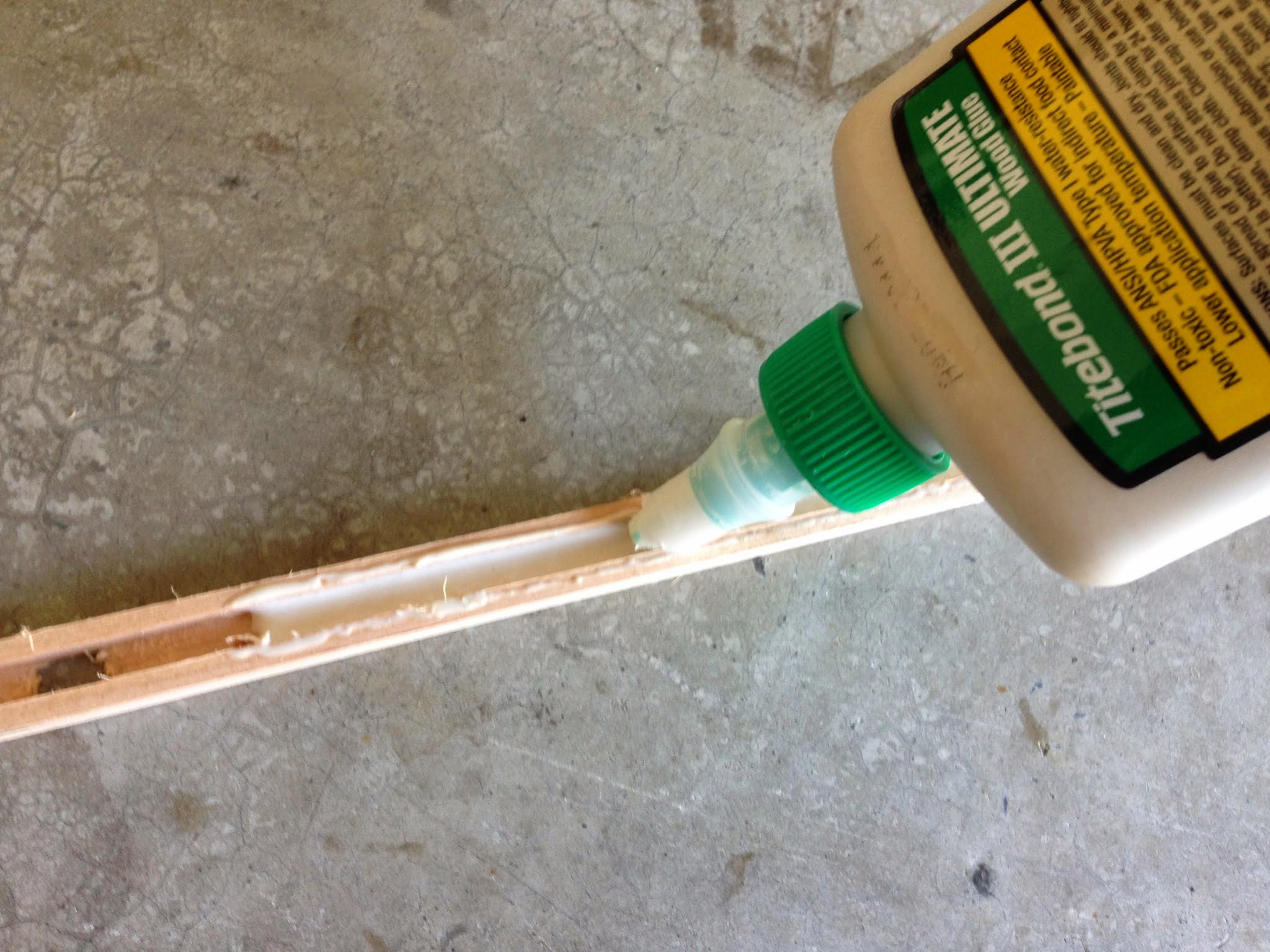
Today I cut 1/4" wide x 1/8" deep slots in all the 1/2" x 3/8" Sitka Pine rib cap strips. I don't have a router, but I do have a friend's drill press in the hangar where I'm building the wings. So, I bought a 1/4" straight-cut router bit, set the drill press to maximum speed, and set the bit's cut depth with the press' table and clamp block. The results are not too shabby. I'm sure the cuts would be less frayed and rough if the bit were spinning at 10,000 rpm, but this will just give the Tightbond III glue more material to grip. |


|


 May 1, 2015: With all the ribs firmly glued in place, I'm now able to cut, trim, and glue the remaining foam D-cells into the empty bays."  Dry fitting the aluminum trailing edge "V's." |
 May 3, 2015 Here's the finished D-cell foam leading edge, all sanded smooth and flat after hot wire cutting the odd numbered bays.  Here's the underside detail of the LE, along with a shiny, new, longer, two-bolt, stainless steel wing strut attachment tang. |
 Laying out, measuring, and marking the cut line for vinyl roof flashing that will provide a smooth bearing surface for the ceconite fabric covering.  After cutting and trimming. The flashing will be glued to the LE and foam with 3M 30NF water-based contact cement. |
 Inter-rib X-brace lacing.  Close up of inter-rib lacing. Two wraps around each rib still allows the rib to move side-to-side, but adding a final third wrap locks it all up. The lacing is a single length, starting on the root compression strut, secured to it with two square knots, Xing back and forth to the tip rib, then looping back around and ending where it started. |


May 15, 2015:
It's on to building the other half of the wing. This is the aftermath of cutting out all the web triangles and ribs from the 4x8 sheet of 1/4" underlayment plywood, fresh from the CNC router. Next up is repeating steps 10 through 31 in the Wing Page... which is just a joking guess as to the number of steps there really is. During this time (I estimate a month or so), I won't be updating this blog (since I've taken all the photos already). However, I'll return with the next big step in assembly... covering with ceconite fabric using my "DIY Stewart Systems™ Method." |

Five weeks later and the port (left) wing is finished!
Here are the two, together at last... ready for fabric covering.
The plan is to take the tail feather frames off the fuselage and cover them first, then do the wings. Learn on the small ones, so no mistakes on the big ones.
September 13 through 27, 2015:
Herein are the details for covering the wing, starting with the process of extending the 70-inch wide ceconite fabric to 80 inches via a simple overlap seam (the wing is 72" at the root, plus add 4" for margins and 4" for rib curvature).
Note: The 3M 30 NF contact cement is very pale in these photos, because I used up my first quart and unknowingly ordered the neutral (cream colored) version of the cement, not the green version. I tried "fixing" it by adding 20 drops of green and 10 drops of blue food coloring to the bottle. Sadly, being that they're dyes rather than pigments, the color fades completely back to neutral on exposure to heat and air, but at least it helps during application.
 Start by cutting backing strips of news- or craft-paper 2 1/4" wide to prevent gluing the fabric to your work table. Draw a pencil line 2" away from the edge of your fabric that you've cut to size. |
 Place a strip of paper under the fabric and begin generously applying glue to the top of the fabric with a 1" foam brush, pushing and working the glue down into the weave. |
 Continue adding strips of paper, butting them up against each other (do no overlap) and gluing the fabric, using the 2" pencil line as your guide for both positioning the paper under the fabric and applying contact cement. |
 Allow the cement to dry for an hour or so, then place the fabric extension on top and overlap 2". With a sealing iron set to 250 degrees, use the tip of the iron to tack only the very edge of the extension to the glue along the 2" pencil line. |
 Then go back over the seam with the full plate of the iron, pressing down hard (use a piece of wood to press down on the nose of the iron as well) slowing advancing at around 1 inch/second. At this temperature, the fabric is only partially shrunk as it is set into the glue, allowing the seam to be shrunk and flattened later on at 275 F. |
 Finish the seam by painting cement back over the fabric, working it down into the weave. Allow to dry for an hour before proceeding to glue the fabric to the wing spars. |
 To make handling the wing easy (like the "big boys") I used two shop light tripod stands and replaced the lights with this little pivot gadget; a scrap of U-channel and an AN-4 bolt. This is the wing tip end where a 1/4" hole was drilled mid-way between LE and TE in the 5/8" OD tip spar. A similar hole was drilled in the solid cap rib at the root end. Getting the balance point took 4 holes to find, but being drilled in wood, they can be easily patched. |
 With the wing balanced on the tripod stands, contact cement was applied to the wing frame just the same as was done for the tail feathers. Here you can clearly see the overlap extension seam for the bottom surface fabric. |
 Unshrunk bottom fabric fully glued to the wing frame. |
 Unshrunk bottom from the opposite side. |
 After shrinking at 275 degrees. Due to the flimsy nature of the 1/4" thick plywood root cap rib, even though reinforced with a compression strut and wood sub-ribs, shrinking at 300 or higher would result in even greater warping of the rib (see the eighth photo below). |
 Holes for the wing strut attachment tangs were not made prior to shrinking the fabric. This allows for precise location of the hole after shrinking, because shrinking will cause an existing hole to "drift" and enlarge unpredictably. |
 Cut a slot for the tangs into the shrunk fabric by melting with a pencil soldering iron, then reinforce with a pre-shrunk patch. |
 Inside view showing glue penetration. |
 Don't forget to run any wires or other accessory items before gluing the top side fabric in place! Though I don't have any now, I will eventually install LED wing tip nav lights/strobes. |
 TIP: Do Not wrap the wires around any of the ribs or secure with square knots, as shown here. You will regret it, because you'll learn, too late, that you won't be able to replace or add to the wires without cutting the wing fabric open to UNDO the knot. |
 The top wing fabric attached to and hanging off the bottom side of the TE. |  Wing rotated over for gluing the top surface fabric to the LE, tip spar, and root rib. |
 Top surface shrunk. If you use vinyl roof flashing, like I did, on the LE "D-Cell," don't be alarmed when it puckers badly as you heat shrink the fabric. Just continue to evenly and thoroughly heat the vinyl, firmly pressing it against the foam blocks underneath. It will soften and "reflow," smoothing right out, as long as your underlying foam blocks have been sanded flat and smooth. |  Guess I should have used a 1" board for the root cap rib instead of 1/4" plywood, but I didn't want to add that much weight to the plane and believe this amount of warpage, although a bit more than expected, will not be structurally critical or impair performance. The cap ribs were already slightly "wavy" due to moisture absorption before applying and shrinking the fabric. |
 Applying 1/2" reinforcing tape to prevent lacing stitches from cutting through the fabric. |  Tapes applied to both surfaces. |
 Chalk snap lines for rib stitch spacing applied every 4". I'm waiting on the arrival of 500 feet of flat waxed rib lacing cord. I already bought what was called rib lacing cord from Aircraft Spruce, but it was not waxed, way too thin, and totally unacceptable for rib stitching. I didn't notice this months before, because I didn't look at the package label when it arrived, which said "Ceconite Hand Sewing Thread." AC Spruce gotz it wrong, boys and girls! The flat stuff made by SuperFlight is what you want or identical material used for marine sailmaking (and 4 times less expensive, because it's not FAA certified). |  Close up. Rinse and Repeat all of the above for the other wing waiting in the background (as of this writing the bottom fabric has been applied and ready for shrinking). |
October 1 through 11, 2015:
Here's a few extra details not shown in the last blog entry.
 To minimize scalloping between ribs when shrinking dacron, start by shrinking at 250 F over each rib, first. Start with the middle rib, alternating left and right every other rib. Then return to the middle and shrink the fabric over the skipped ribs, again, alternating left, then right. |
 Continue shrinking between the ribs, alternating from the middle outward, left, then right. Repeat the whole process again at 275 or 300 F. |
 Melted holes make it much faster to locate the needle on the bottom by touch and a much cleaner hole than those made by needle or pencil pokes. | |
 Ribs laced using the SuperFlite knot (see video below). |
 Measuring 2" wide pinked-edge finishing tapes. |
 Gluing the finishing tapes down by applying a generous amount of contact cement, 12" at a time, with a 1" foam brush... |
 ... then laying the tape over the wet glue and painting more cement on the tape, aggressively working it completely and thoroughly into the tape. Brush back and forth several times to evenly spread and sop up the excess, until the tape is basically "dry" and free of brush marks and glue ridges. |
 Two down, 11 to go... |
 It took about 4 hours to glue all 13 rib finish tapes down on just one side of the wing. This was done on a warm, dry day, so by the time the last rib was done, the first tape was dry and ready to have its pinked edges heat "sealed" using the sealing iron set to 300 F, followed by the others on down the line. |

(there is no sound on this video)
January 28, 2016Four World War I British-style roundels were painted on the wing tips (top and bottom times two wings). Each one took 3 - 5 days to create. This video shows you how to paint them.
The process shown here is:
- Make a series of string compasses (measured lengths of thread, a push pin, and an ink pen) to draw out the various sizes of circles of the roundel.
- Spool out several feet of 1.5" wide Frog Tape brand painter's masking tape and cut a 1/4" wide strip the full length.
- Mask the outer-most circle with this thin "pin stripe" tape.
- Tear 3"- 4" lengths of the remaining tape and place them around the outside circumference of the pin stripe mask.
- Brush on a thin line of paint around the inside edge of the pin stripe mask using the same color as the base. This activates the tape's sealing "gel" in its adhesive, preventing the desired ring color from bleeding under when this thin band of sealing paint dries.
- Paint the ring the desired color using a cabinet-grade fine foam roller. Repeat one or two coats more when each is dry.
- Remove the masking tape.
- Redraw the next inside ring that's been painted over and repeat steps 2 - 7.
| May 19, 2020: |
| I decided to conduct an experiment to see if I can reduce RFI from my LED strobes. This required gaining access to the unshielded power wires inside my wings, in order to replace them with two-conductor, shielded cables (100% foil wrap with drain wire). This entailed the addition of an inspection hole in the underside wing tip, so that I could untie the individual power wires from the wingtip rib and more easily wire up the wing tip nav strobes (including the addition of two ferrite chokes as close as possible to the lamps). For the tail strobe, I replaced it's 4-conductor, shielded cable (which I did not ground, for some unknown reason) with a 2-conductor and grounded the shield, connected to the negative side of the terminal strip inside the instrument panel.  Standard 4-3/4" diameter inspection hole rings and recessed covers from Aircraft Spruce.  I glued the rings to the painted fabric with 3M 30NF contact cement (same stuff the Stewart System uses), then overlaid it with a circular "patch" of dacron/ceconite. I used the tip of my aircraft iron to "activate" and bond the fabric along the inner and outer circumferences of the ring, then covered the patch with glue, wiping off the excess, standard Stewart System style. |
 It took five thin coats of exterior semi-gloss latex paint to cover the glued patch. When dry, I cut out the hole with a razor knife. Precision not required.  Strobe power wire replacement complete. On go the painted covers. |
| May 22, 2020: | ||
| The experiment didn't work. RFI noise is exactly the same as before (squelch breaking level 7 in certain areas of the sky where terrestrial RF transmitters are present). This must mean RFI is being radiated directly from the LED strobes themselves and not from or through the +V power lines. The only way to verify that theory is to power the strobes from an external DC power source, in order to 100% isolate them from the instrument panel and radio. | ||
| May 23, 2020: | ||
I did some more investigation today by using the radio, handheld with its rubber ducky antenna, to sniff around the trailered plane. I powered the instrument panel with a 14 volt DC power supply. Turns out that the wing tip LED strobes are not emitting RFI from the new shielded power cables and only very weakly from the lamps themselves. However, the tail strobes very much do, despite the presence of THREE ferrite chokes and a 0.1 uF capacitor installed on the leads coming out of the lamps. Then I discovered that the new fuel level sender was putting out a constant whine, so I added two clam shell chokes on the leads coming out of the sender, along with a 0.02uF cap across +V and gnd. This cleaned up that noise nicely, though it wasn't very strong to begin with. This left the puzzling reason of why the pulsing tail strobe RFI was coming down its shielded power cable that runs the length of the boom. I found a strong node of radiation coming from it right above my head, so I put two clam shell chokes on the cable at that location. This significantly reduced the noise. Now to test it all again with the engine powering everything, which adds around 2 squelch "units" of its own hashy noise to the mix.
|
Can't wait to see the wingfold mechanism. Do you think you can still stay 103 compliant weight wise?
ReplyDeleteThere won't be a wing fold. They will be taken off and placed in cradles on my trailer just like sail planes do.
ReplyDeleteRe. 103 weight... probably going to be 30 over. Haven't weighed the uncovered frame and engine yet, but predict it will be around 195. I predict the wings will be around 75.
I like the looks of this wing design. Thumbs up.
ReplyDeleteWow! Great workmanship and 'smart'. (Posted by a guy who had a pro-build shop for 22 years). And, a really great presentation here.
ReplyDeleteDean,
ReplyDeleteIn the late '70's I built a Weedhopper Gypsy. While intrigued with the basic Weedhopper it was 2 control and I was very apprehensive about that (licensed pilot). The Gypsy got ripped out of it's tie down in 100+ mph winds and thrashed to pieces the day after I took it to the airport. Never got the Chotia 460 to run more than a few seconds. Maybe it was all for the good? I was never real happy with the load paths that looked like last nights spaghetti dinner even though they seemed to fly OK and not too many folks seemed to get killed in any of his creations.
I have come to believe the original (or follow on versions) of the Weedhopper are probably pretty nice, safe little airplanes. In fact I am about to set forth building one. I like the effort you have done with the wing and it sets me to thinking about how I might go about doing that myself. I also am seriously considering straightening out those pesky load paths where I see them (almost everywhere, actually) and cleaning up the exposed airframe components. Every ounce of drag removed converts to climb performance. I live in a desert, it's important. I also insist on keeping the thing 103 legal.
What you have done with the Skyhopper is inspiring. Keep up the good work.
This comment has been removed by a blog administrator.
ReplyDeleteTapered chord from 6 ft root to 3 ft tip. Root camber = 8.5" Tip camber = 4.5"
ReplyDeleteThis is new to me.How did you get the wing ribs converted to CNC files?
ReplyDeleteThe Vcarve Pro software imports Adobe Illustrator .ai files. The file has two layers... one for the web cutouts and one with the outline of the airfoil. I simply selected the cutout paths layer to be the first round of cuts, and the airfoil outlines as the second cut. Vcarve did the rest (adding partial 1/4" wide connecting "break away" tabs, that were a singly ply layer thick, to keep the cut material in place, etc.).
DeleteWould you be willing to share the CAD files for the airfoil ribs?
ReplyDeletecan you tell me the wingspan
ReplyDeleteHello, very good afternoon, a query exists for the possibility of obtaining the CNC cutting format, for me to manufacture the wings.
ReplyDeleteThank you very much, greetings from Chile
Mr Dean Scott the link you put above does not exist can you supply me with the information to make one
ReplyDeletemy email: Ha.alakhali@gmail.com
Links updated. I shutdown my domain.
Deletethank you so much.
Deletegratefully.
Hello... Does anyone have any old aircraft to donate (free of charge) for an aviation museum project? Many thanks
ReplyDelete