 April 25, 2014: Gusset plate layout on .025" 6061 T6 aluminum sheet.  Cutting out gusset plates. |
 Red lines are the half circumference point on the 1" OD tubes these plates will be wrapping around.
 Bending by hand around a 3/4" OD tube. Spring-back of the metal causes the wrap around to perfectly fit a 1" OD tube.
 |

Takes about 5 minutes to bend each gusset, because the top and bottom of the gusset are not parallel due to spring back after bending around the tube, so you have to apply a lot of thumb pressure to over-bend each side around the tube, remove the tube, and then squeeze and push and squeeze and bend by hand.
|
 April 26, 2014: Using the OEM rudder frame with a slight modification: cutting the lower arm even with the upper arm and replacing the LE with a 2" longer tube.
 Gussets pop riveted. Frame is just as strong, if not more, than the OEM bolted sandwich plate design. |
 April 29, 2014: Squaring up the new vertical stabilizer. Top section above the boom shown. Made from salvaged 1" x 065 tubes. 058 wall tube would've been better and lighter, but since the OEM tail group was constructed of 065, that's what the new parts are made of.  Bottom portion of vert. stab. Gap between the black tubes is where the 2.5" OD main boom goes. Bolts will go all the way through them and the boom to hold the fin in place. |
 Gussets pop riveted. Instead of triangle gussets on the TE holding the horizontal spreader tube, 1" straps are used so that a small opening in the fabric can allow a socket or crescent wrench access to the vertical bolt going through the boom. The front bolt goes through the spreader tubes, top to bottom, at the short, forward extensions, outside of the fabric.  The completed frames of the vertical stabilizer. Just need to fabricate and attach upper and lower hinges for the rudder. |
 April 31, 2014: OEM tubes of the horizontal stabilizer and elevator after slight modifications, namely, cutting the LE of the stabilizer in half and removing 3" between the two halves, and cutting an inch off each of the elevator's outer ends to make its TE parallel to the added LE tubes.  May 1, 2014: Gussets pop riveted. Notice the use of the OEM bolted sandwich plates on the inner ends of the elevator. This is where new elevator horns will attach. I'm debating whether to replace these 1/8" thick plates with gussets and simply bolt in the horns without the top plate. |

June 2, 2014
Made the boom brackets and hinges for the horizontal stabilizer out of 1" x 1/8" 6061 T6 bar. Shown here are the longer pieces that will be bent into "U" hinges. Shorter lengths were cut and bent into "L"s as seen attached to the boom below. |


June 3, 2014: Details of the vertical stabilizer attachment (vertical bolts and nylon saddles) and the horizontal stabilizer hinge brackets "L"s fore and aft.
|


Details of the horizontal stabilizer hinge assembly ("L" + "U"). What you can't see are the 1" diameter milk jug HDPE (high-density poly-ethylene) plastic washers between the boom hinge brackets ("L") and the stabilizer hinges ("U"). These provide friction protection from metal-to-metal contact.
|
 Aft end of the boom showing attachment details. Note the horizontal AN3 bolt (used for mounting the aft h-stab hinge brackets) passing through the TE of the vertical stabilizer. As predicted, the tail group is VERY RIGID!  Horizontal stabilizers in flight position. They are held up by hinge bolt/nut friction for this photo. OEM-style brace struts will be added. I'm debating whether to fabric cover the v-stab in place or take it off and make access "ports" in the aft corners at the boom to get to the boom attachment bolt. The bolt is a really, really tight fit and small holes in the fabric for tools to access it would make the installation/removal process all the more tenacious if the assembly needed to be removed. |
 
H-stab can be folded down or folded up for transportation/storage.
|
 
June 4, 2014: Fabricated these horizontal stabilizer strut brackets and mounted them to the TE spar (left). Why? Because the OEM method of attaching the strut directly to the TE will be covered by the ceconite/stits fabric, thus I needed a "tab" to protrude below the fabric.
Mounted the OEM lower strut tangs to the bottom of the lower vertical stabilizer (right). There is no 1/4" or 5/16" all-thread rod any more, per the OEM Weedhopper design. It's been replaced by the 1" OD, full-length v-stab TE tube. The h-stab struts are OEM 5/8" OD 6061 T6 tubes. |
 
June 9, 2014: Riveted hinges to the h-stab TEs and elevator LEs and mounted the elevators with AN3-4 bolts. I think I'll use AN3-6 instead (1/4" longer) in order to get more threads out of the nut (currently flush).
Max down deflection is 36 degrees (about 10 deg. more than OEM). Max up deflection is "infinite"... well, as much as the stick will allow, but as you can see above, the elevators can fold over on top of the stabilizers for transport when the stabilizers are folded down, which points the elevators horns outward (otherwise they'd impale the vertical stabilizer). If the stabilizers are folded up, then the elevators remain in the neutral position, which, again, points the horns outward. Speaking of horns, I'll be cutting, bending, and mounting them shortly. |
 
Close ups of an elevator hinge (Left - elevator folded over top of stabilizer. Right - elevator neutral) See Misc. Fabrications for construction details. Note that I've hammered the downward pointing "tab" flush with the tube for a cleaner, smoother fabric covering. The "tab" facing upward can remain flat as it will be parallel with the fabric.
|
 
June 10, 2014: I took Bob Gregory's advice about placing the rudder horn near the boom to prevent the rudder cables from pulling on the bottom of the rudder where the OEM rudder horn is located, which twists the tail group. In order to two that and kill two birds with one stone (provide a place to mount the rudder horn AND reduce rudder frame deformation when shrinking the dacron fabric covering), I added this reinforcing spar (left). Right shows the rudder horn mounting details.
|
 
June 11, 2014: Rudder mounted and close up of rudder horn position about 1/2" under the boom and how it clears (full right or left) the elevator (neutral shown, but even at full down).
|
 
Close up details of the rudder hinges. They're made from 1 1/8" C-channel (same as the axle brackets). Each is 3/4" wide with 3/8" of the arms of the C cut off and rounded to clear the AN3 bolts (left is bottom hinge, right is top).
|
 June 27, 2014: New elevator horns laid out on 1/8" 3003-H14 aluminum plate, ready for cutting with the jig saw.  Elevator horns cut and ready for drilling, filing (rounding corners, smoothing cut edges), and bending. |
 "Styling" and shaping finished. How did I bend these? By hand. I simply clamped the short arm in a table vise padded with a towel, placed the dashed bend line 1/8" above the top of the jaws, and pulled the long arm down. This made a nice 1/4" radius bend naturally, no stress cracks, etc. The bend radius at the long arm's angled edge ended up being a bit larger due to the edge being at an angle to the short arm's straight edge, so I lightly pound on the long arm at the angled edge bend with a hammer to tighten up the bend.  Installed. Required moving the inner-most elevator hinge to the right a 1/2" to make room for the lower right mounting bolt. That is, Mr. Designer didn't see that coming. |
 Never let 'bum' parts go to waste! These are the 'old' seat tubes I saved after needing to remake them with a longer rear extension past the axle (see "Cockpit" page for details). They were nearly perfect for making the new elevator wishbone yoke. They just needed slots cut into the ends for the horns to slip into and minor tweaking of the bends so they fit the spacing between horns without binding.  Elevator yoke attachment to the horns. Notice the use of milk jug plastic "washers" between each side of each horn and the slots in the yoke tubes to prevent metal-to-metal contact. |

Installed the tail wheel (no, not a tail dragger) to protect the rudder from dragging on the ground. |


| |
| July 10, 2014: To solved the problem of how to bolt the tail wheel and horizontal stabilizer struts to the bottom of the vertical stabilizer AFTER covering the v-stab with fabric, I installed these 1/4"-28 blind nuts that are held in place by 1/8" rivets. Now instead of dropping a bolt through the tube from top down and using a nylock nut on the bottom of the tail wheel mounting bar, I reversed the bolting direction and pushed it up from the bottom, screwing it into the blind nut. I'm using a split-ring lock washer under the bolt head, even though the blind nuts are self-locking by virtue of being squashed slightly oblong by the manufacturer. | |
 July 17, 2015: The next series of posts will detail the "DIY Stewart Systems" method of gluing and covering Ceconite cloth (a brand of unsized/shrunk dacron polyester) to the tail feather frames (elevators, horizontal and vertical stabilizers, and rudder). |
 To start, I taped over all the "sharp" edges and bumps created by rivets, gusset plates, hinges, and bolts using ordinary cloth athletic tape you can get at any store with home health and medical supplies. |
 Next, I cut the dacron with a 2" margin. |
 The Do-It-Yourself part of the "DIY Stewart Systems" is this nice quart bottle of 3M 30NF water-based contact cement, the exact same stuff Stewart Systems buys in bulk, repackages it as "Ekobond," and sells for up to $10 more. Be sure to use a synthetic bristle brush and keep it moist (wrap it in a wet cloth or submerge it in a cup of water when not in use) or else the glue will start glumping up and gluing bundles of bristles together. In other words, don't set the brush down exposed to air. |
 Starting with the bottom of a flight surface, paint a generous, but smooth, amount of glue on to the bottom half of the framework and taped-over protrusions. It's best applied when ambient air temp is below 90 F and humidity is less than 50%. Do not apply glue past the bottom center lines of any curved part in order to allow the fabric to come straight off the bottom curvatures (tangent or parallel to the flight surface). But do glue past the top center lines. Allow the glue to dry to a tack. |
 Press the fabric in to the dry, yet tacky, glue. Use a small aircraft fabric iron set to 350 F to "tack weld" the fabric along a thin line around the framework, pulling the fabric slightly taut. When the fabric is secured, go back over the framework with the iron to bond the fabric in to the rest of the glue, eliminating any puckers and unadhered edges after trimming off the excess. Apply glue on to the fabric in one foot sections where it makes contact with the framework and wipe the excess glue off with a clean shop paper towel. |
 After the glue is dry, shrink the bottom panel with a clothes iron calibrated to 250 F, then repeat all of the above for the top surface. |
 Use pinking shears to trim off the excess fabric of the top surface. This helps prevent fabric unraveling. Again, use the small iron to bond the edges in to the glue and then go back over the bonded area with more glue on top of the fabric, wiping away the excess. |
 Here's the top of the starboard elevator after the first shrink at 250 F. |
 And the bottom. |
1" pinked finish tape will be glued to the bottom where the top surface wraps around to the bottom, leaving a ragged, uneven perimeter. Pre-shrunk fabric patches will be placed around protrusions, like the control horn, in order to provide structural support and stiffening of the cut made in the fabric.
The whole process of covering this one elevator (first time rookie) took about 4 hours. The first 2 hours were done at night when humidity was on the increase as the air cooled off (temp in the hangar was still around 90 F). Even though the glue was tacky dry, the fabric would not adhere when pressed in to place. It took some coaching with the small iron to get a thin bond line to take hold.
The next day, before the sun set, the hangar temp was above 95, but the humidity was lower. Under these conditions the fabric stuck better with firm pressure and held firmly when "tack welded" with the small iron. So apparently humidity plays a big part in the "stickability" of dacron fabric to 3M 30NF.
August 18, 2015:
A month has passed since I started covering my tail feathers, so how about an update?
The main reason it's taking so long to get this phase of the project completed has been due to the 95+ daytime high temperatures and 50+% humidity. Both have finally abated this and last week, allowing me to get things done without baking in the 105+ deg hangar. That and it takes 3 hours to simply cover ONE side of a flight surface.
Since I covered the basic procedures of covering in the last post (July 17), I'll just post pictures of the progress with any extra notes added. As of this writing, all four horizontal flight surfaces (right/left elevators and stabilizers) are finished and ready for paint.
 Confession time... I didn't think it would, but it did... the unbraced span of the first elevator's LE (where the hinges reside) bowed inward at the center by about 1/8" under tension from shrinking the fabric. This is now being prevented by adding these 3/4" OD tubes. If there is enough fabric left over, I'll redo that surface and add in two braces similar to what's shown here for the right horizontal stabilizer. |
 The ends of the internal brace tubes are shaped to fit the 1" OD contour of the flight surface frames by filing them with an eighth round file that just so happened to have a 1/2" radius. The tubes are held in place by friction, except for here on the slanted sides of a frame. Such require a "tab" and an 1/8" rivet to prevent the end from sliding out of place. |
 Right H stabilizer cleaned, taped, and ready for glue. |
 Finished bottom side. |
 Backing up a bit... Application of 1" wide, pinked finishing tape to the bottom side of the left elevator, covering over the ragged edge of the top surface that wraps around to the bottom. Glue was applied, allowed to dry, and then the tape ironed in to it. |
 Finish tape is cosmetic only, not structural, so in order to save glue, I used 1" tape, otherwise, the common practice is to use 3" or 4" tape and wrap it around the frame edges, centered on the tube so it covers both sides equally. |
 To get the tape to curve around the bends, you press the iron flat on the tape and pull the tape gently as you advance the iron around the bend, the tape shrinking accordingly. Not shown is the application of glue to the top of the tape in short sections, wiping off the excess. |
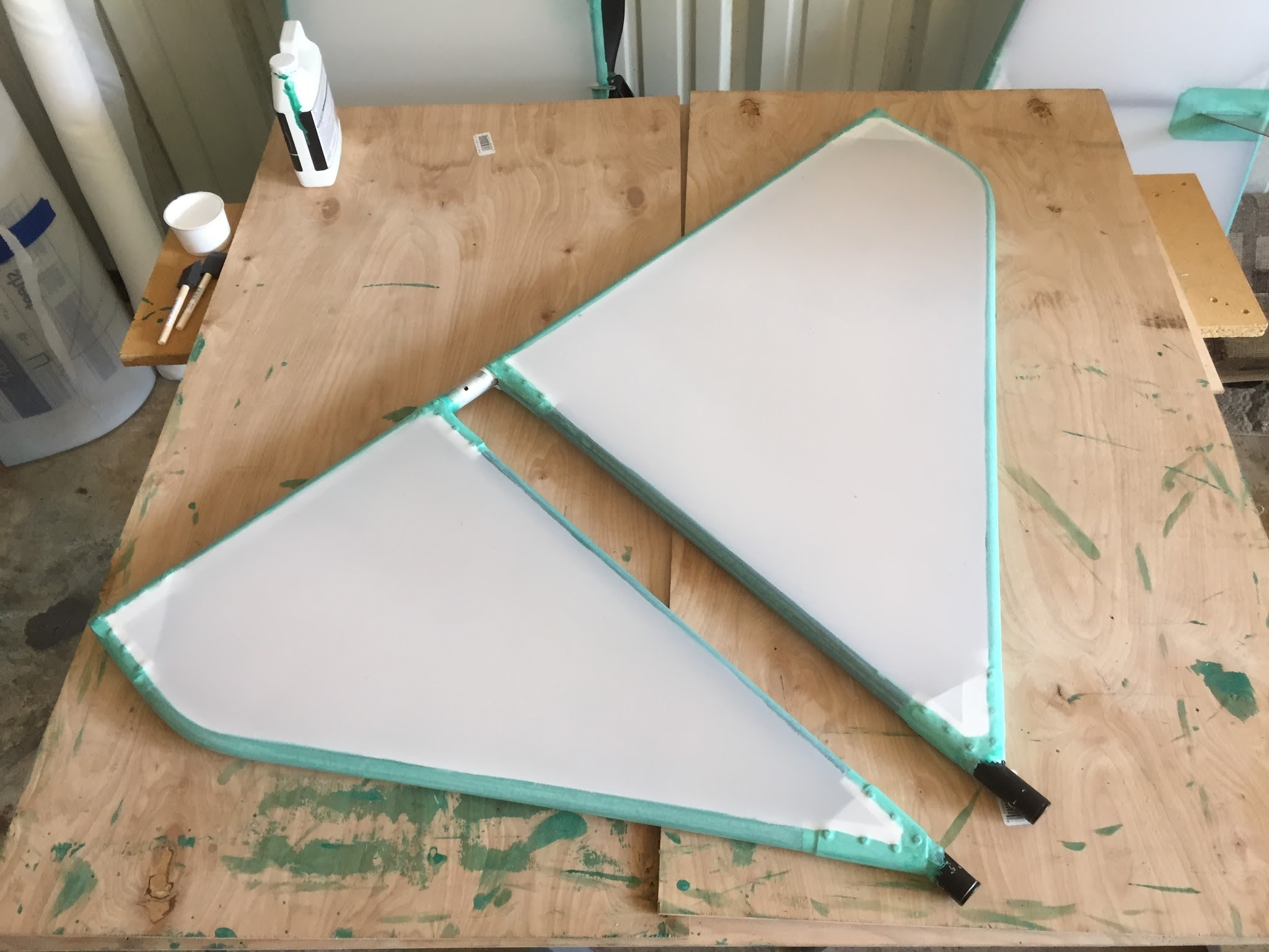
 On to the rudder... frame cleaned with acetone, rivets and sharp edges taped, and ready for glue. I removed the rudder horn and top/bottom hinges. This made working on it easier with less cutting and forming of the fabric around these protrusions.These items will be reattached after the first surface is applied and shrunk, but before the opposite surface is applied. |
 Glue is applied only up to the top center line of the tubes (where the fabric begins touching the frame), however, glue is spread past the center line on the opposite side, since the fabric will wrap around to the inside of the frame. |
 Rudder frame aligned to the fabric, which was cut to size with a 2" margin prior to applying glue to the frame (remember to cut two pieces). |
 |
 |
 |
Top Left: Applying heat to "activate" the dried, but still tacky, contact cement. Again, Ceconite 102 fabric does not stick to the tacky glue when the humidity is above 60%. Heat is needed to help the process. Once tacked into place, you go back over the remainder of each tube's circumference, shrinking the fabric as the heat (about 350 F) sets it into the glue.
Top Right: Fabric fully adhered to rudder frame, showing how it wraps around to the inside of the frame opposite the flat side. Left: Top surface showing how the glue only goes to the center line of each tube. |
August 20, 2015:
 Continuing with the rudder... both sides shrunk. |
 Detail of rudder horn reinforcement patch. |
 Vertical stabilizer cleaned, taped, and ready for glue. |
 Finished bottom side. |
 Top side finished, ready for shrinking. |
 Shrinking fabric of V stabilizer. |
 Pretty. |
 Holes cut (melted actually with a soldering pen iron) on one side only in order for tools to gain access to the 1/4" bolt that secures the V stabilizer to the boom. Contact cement applied and dried, ready for the two reinforcement patches to be glued down over the cut outs. The holes will be reopened after everything is painted. Holes cut (melted actually with a soldering pen iron) on one side only in order for tools to gain access to the 1/4" bolt that secures the V stabilizer to the boom. Contact cement applied and dried, ready for the two reinforcement patches to be glued down over the cut outs. The holes will be reopened after everything is painted. |
August 27, 2015:  Tail surfaces ready for primer! Left to right: Vertical Stabilizer, Rudder, Port Horizontal Stabilizer, Starboard Horizontal Stabilizer, Port Elevator, and Starboard Elevator. | |
August 28, 2015: Now begins the awesomeness that is painting! I'll be using common household interior and exterior latex. First two coats will be interior primer, followed by two coats of exterior semi-gloss finish. Any brand should be good. Valspar at Lowes has a high rating and happened to be the cheapest at $13/gal for the primer and $22/gal for the semi-gloss. Both were tinted to a WW1 olive drab (the primer did not reach even half the tonal value due to it being pure white, versus the finish paint being the required neutral base for proper color tinting). In order to obtain the smoothest finish possible, Floetrol, by Flood, and ordinary automotive windshield wiper fluid are used to thin both primer and finish so that brush or roller marks flow and smooth out as the paint dries. | |
 Ingredients for thinning latex paint (primer and finish): Regular automotive windshield wiper fluid, Floetrol latex conditioner, 4" foam cabinet paint roller, 24 oz mixing/measuring cup. |  Measure 2 oz of Floetrol. |
 Add to and mix vigorously and thoroughly 2 oz. of wiper fluid. |  TIP: To keep your paint can's lid groove free of paint while pouring, fold up a sheet of paper towel and jam it into the groove with a screw driver. |
 Pour paint into mixing cup up to the 24 to 26 oz line. This will give you a 15% thinner-to-paint ratio. Mix vigorously and thoroughly. Depending on temperature and humidity, you may want to thin 20% or more. Pour paint into mixing cup up to the 24 to 26 oz line. This will give you a 15% thinner-to-paint ratio. Mix vigorously and thoroughly. Depending on temperature and humidity, you may want to thin 20% or more. |  Remove paper towel from can rim and discard. Replace lid in nice, clean groove. |
 Pour around 2 - 3 oz of thinned paint from mixing cup on to a flat piece of plywood rather than in to a roller tray. They say it makes for a more even saturation of the roller... |  |
 Application of the first coat of interior latex primer. Roll out in sections this wide, or until the roller runs "dry." Then go back over several times with the "dry" roller to even out the overlaps and paint ridges. Do ONE side at a time, letting it dry a full day before doing the other side. |  Applying the second coat 90 degrees to the first.Remember to tape off any protrusions (control horns, hinges, etc.) that you don't want to scrape clean afterwards. Applying the second coat 90 degrees to the first.Remember to tape off any protrusions (control horns, hinges, etc.) that you don't want to scrape clean afterwards.
|
August 30, 2015 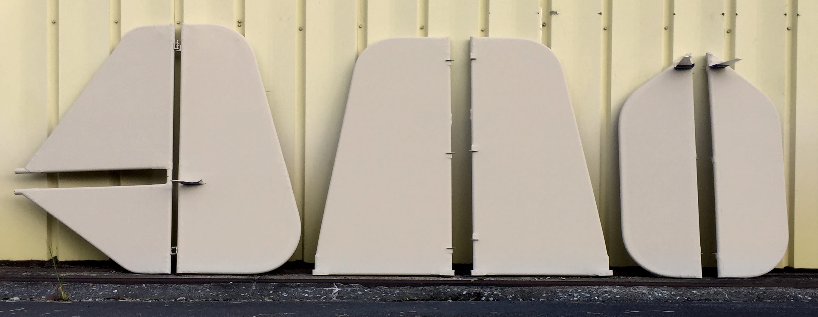 Tail surfaces after two coats of interior latex primer. | |
September 6, 2015:
The tail is finished! The tail is finished!
 Two coats of "olive drab" semi-gloss exterior latex finish on all surfaces, except the rudder. It only has one, because I wasn't sure how I was going to finish it before the maiden flight. As you can see, I decided to finish it per my Sopwith Camel scheme. Blue and white have two coats, but the red required four. For some reason the pigment was not really that opaque compared to the blue (same paint base). I will, however, wait to paint roundels on the wings until after the maiden flight... just in case, however unlikely it may be, the first test flight encounters, well... "catastrophic" problems and all this work becomes a twisted pile of wreckage on the runway. Nah.... it will never happen, right? |
August 19, 2018
Oh, why not? Skyhopper needs a tail decal, and since she has a WWI Sopwith Camel livery, it's only fitting that this is Snoopy's domain, where he curses The Red Baron.
 I started with frame grabs from the classic TV show, "It's the Great Pumpkin, Charlie Brown." that features the famous, imaginary dog fight sequence between Snoopy and the unseen Red Baron. I loaded the images in to Adobe Illustrator and sketched over them to get this composite pose from a standing, fist-in-air shot and an angry seated shot. I then added my own modifications (teeth and angry goggles). |
 After adding my Skyhopper logo and sizing it to fit my upper vertical stabilizer, I uploaded it to VistaPrints.com, and ordered two, 1-1/2 foot by 2 foot automotive vinyl decals (one for each side of the v.stab). They arrived a week and a half later! |
 The decals were printed on clear, non-die cut, adhesive vinyl, so I had to cut along the edges of Snoopy. I didn't do that for the logo, because I didn't want to deal with aligning and placing individual letters, so I just cut straight across the top and bottom. This the dry fit using bits of electrical tape. |
 After peeling the backing paper off in sections and lightly pressing the decal on to the cleaned v. stab, I burnished it down with the back of my finger nail from the center out to the edges. |
 Not bad for $12 per sheet! There's not many printers that do one-offs like this. If they do, they charge twice to three times what Vistaprint does. |
 After several flights, amounting to about 3 hrs, they are staying nicely adhered to the painted dacron fabric. |
Great job on the re-design of the tail group......I'm glad to see people working on updating the 'hopper. I think it still has a great deal of potential especially for rookie aviators. I built a Gypsy many years ago. it was a little crude but worked. I bought it because it was 3 control, odd for the time now I`m going to build a `hopper because it`s 2 control!!! You're articles have inspired me to push ahead.
ReplyDelete