
May 8, 2014
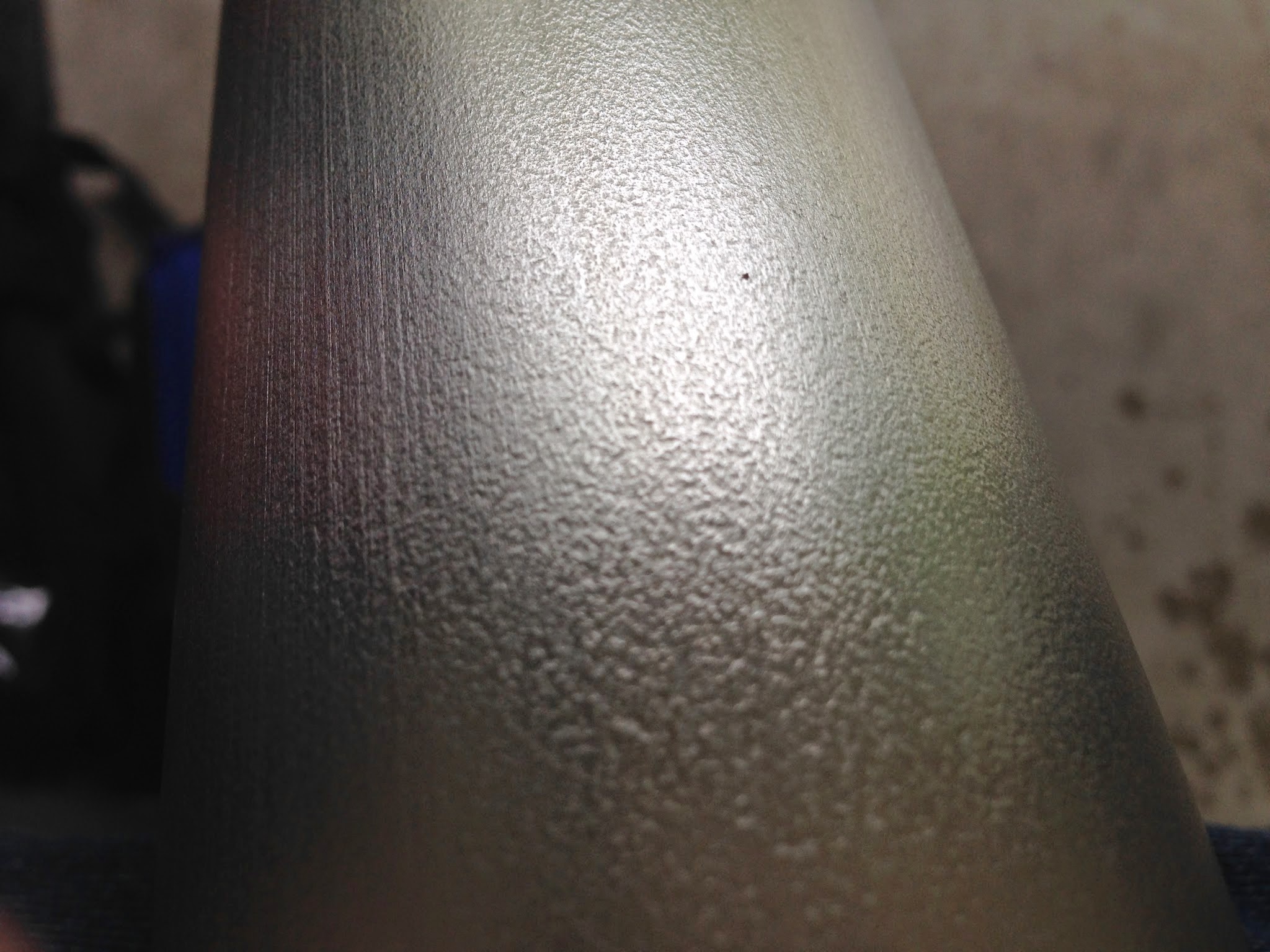
I'm super bummed! The 2.5" x 065 tube from Alcoa has a bumpy surface finish instead of smooth. So, after Scotch Brighting one of the two tubes to remove oxide, handling marks, and the laser-etched manufacturing info (lot #, size, mill, etc.), I applied a few dabs of Mother's and rubbed it in. Tube turned black, so I know it was "working," BUT, after removing the black haze with a clean towel, the tube did not become a mirror-like shine. Instead, it remained a few shades darker than the untreated surface because the polish remained in the micro valleys of the bumpy texture. I sprayed Simple Green cleaner and BAM! the polish just washes right away, leaving the tube identical to the untreated portion. No chrome-like finish for my main boom. >:-[ The other 1" and 1.5" tubes have a smooth, flat finish that should mirror up. |
 |
May 9, 2014
Close up of the fine, bumpy texture on just the two tubes for my main boom. I tried wet sanding a 8" section with 150 grit paper. Barely made a dent. So, I guess I'm stuck with this permanent "satin" finish. |

Tools and pieces required for splicing 2.5" OD x 065 tubes together (an 8 foot and a 7 foot) to make the Weedhopper's 15-foot main boom (some call it a keel).
Get the Splice Template PDF here.
|
 The internal splice sleeve is inserted 6" in to the end of one tube, then the other tube is carefully slipped over the remaining 6" of the splice. Since this is the same template I used to drill and splice the previous boom, it was just a matter of aligning the existing holes in the splice sleeve with the paper template to guarantee that drilling the dots on the paper and through the tubes would be exactly where the existing holes were.  After drilling, removal of template, and deburring. |
 I only riveted one end so that I can pull the tubes apart in order to drill the holes in the boom for the frame tubes and structures. Not enough room in the shop for maneuvering a 15-foot tube on a small drill press.  Ain't she purtty!? |
 May 12, 2014 The next 9 images show how I cut the rounded notch at the back end of the boom for holding the trailing edge (TE) tube of the vertical stabilizer. The end of the boom has a 2" long piece of 2" schedule 40 pipe (left over from the boom splice and motor mount sleeves). This material is around 1/4" thick.

|


|


|

Like so.
The 3/16" pop rivet holds the sleeve in place. The 1/4" vertical hole going through the sleeve is for one of the vertical stabilizer's 5 1/2" long attachment bolts that will pass through the top v. stab. spreader bar, a nylon saddle spacer, the boom, another saddle spacer, and the bottom v. stab. spreader bar. Additionally a 3" long 3/16" bolt for the horizontal stabilizer's pivot hinges (one on either side of the boom) will pass horizontally through the center of the v. stab. TE tube. The combination of these three anchoring methods will make for a very rigid tail group, compared to the OEM method of using a 5/16" threaded rod that attached only to the bottom of the boom and required a set of brace tubes going from the bottom of the rod to the main axle. This redesign eliminates those two lower rear brace tubes. The three methods are: notch, 1/4" vertical bolt, and 3/16" horizontal bolt. |
 The finished 1" OD rounded notches...  ... that snuggly hold the TE tube of the vertical stabilizer frame. |
 May 13, 2014: Drilled the holes for the boom's fuselage and tail group, so now I can rivet the two sections together.  One 15 foot, 2.5" boom, ready for stuff. |
 
May 29, 2014
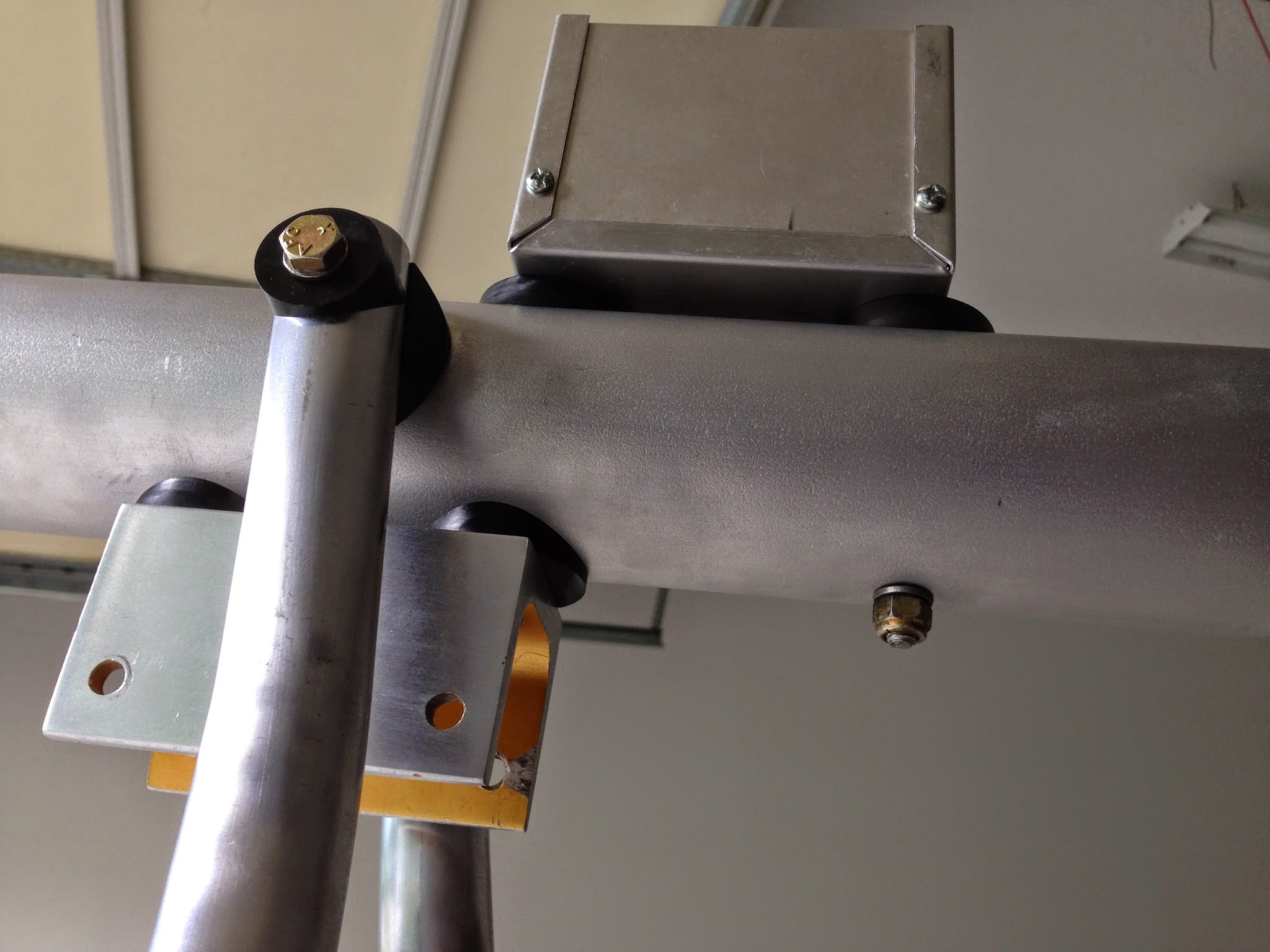
Received in the mail today my custom selection of injection molded nylon 6/6 saddles from Scott McClure's WeedhopperUSA.com store. Here's how they look on the center fuselage brace. I used two flat faced saddles for mounting my Tomar NEOBE 400-1228 dual-head strobe power supply to the boom. The aluminum project box is for neatness and a bit of RF (radio frequency) shielding. NEOBE type strobe units were used by law enforcement before LED flashers became common. They fire at a constant 12 pulses per second, alternating 6 pulses between two strobe heads. The visual effect of the 20 watt xenon tube flashing 6 times in a half second is an apparent brighter, longer-lasting, near constant illumination. The tubes receive a lower voltage than single flash strobes, so the tubes last longer. The power supply itself produces a very audible ticking sound (12 ticks/second). Sadly, I can't find anyone selling this particular power supply any more. I bought it as a package deal (supply, two 20-watt helix tubes, and two 15' shielded cables) from an online store that sold all sorts of emergency and law enforcement systems for $120 back in 2005 or so. Now all those sites are gone. The brown wire wrapped around the ferrite clam-shell choke is the 12-volt power lead. The choke prevents RFI from getting into other devices, namely my radio and Magellan GPS, connected to the same power buss. Power and cables coming from the two strobe heads enter through the square opening. |
Nose strut bracket with flat-faced nylon saddles. Nice, firm foundation. This bracket was scavenged from the four used on the wing LE and TE spars for attachment of compression / thrust-drag spars.
Notice I sanded and filed off the gold anodizing. Why? Simply aesthetic reasons. But due to it being so deeply applied (or maybe age) it was too hard to try and do the inside surfaces, so I gave up. |
How are the brakes holding up?
ReplyDeleteI may do the same on my Hooiser Hopper
The fibrous brake band material lasts forever! So don't get the cheap rubber-based brake material bands from Northern Tool! Been there, done that. Lasted a few landings and they were toast. These band brakes have good stopping power when properly tensioned. They can hold the plane in place at near 4,500 rpm. At 6,100, the 503 will make the locked up tires and my ground-planted Flintstone foot brakes that are gripping the nose wheel between them, skid on pavement.
ReplyDeleteI used your brake install pictures a LOT to build mine. Thanks for the guidance. I've got the drums, and bands installed. I drilled out the 7/8ths inch brake handle to 1". That was a challenge, but now it's installed below the rubber handle. I've ordered parts to install the cables. I also ordered 3/8ths bolts, I only had 5/16ths. If the 5/16 bolts break, I'll update them, or if I have spare time. Yours looks a lot neater than mine, but I think mine will work.
DeleteThis comment has been removed by the author.
ReplyDelete
ReplyDeleteIt seems your brake band is on backwards. The movable end of the band MUST be pulled the same direction as the drum is turning! This allows the band to assist in the stopping effort by gripping the drum to help pull itself tighter. Band-wrap. A type of self energized braking. Greg Kess.
The free end IS being pulled in the direction of rotation! If it wasn't, the brakes would be ineffective, as you've noted. Look closely. I use photos from both sides. The anchored end is in front of the axle. The lower fuselage tube shown supports the empennage (tail), NOT the engine!
Delete