May 4, 2014
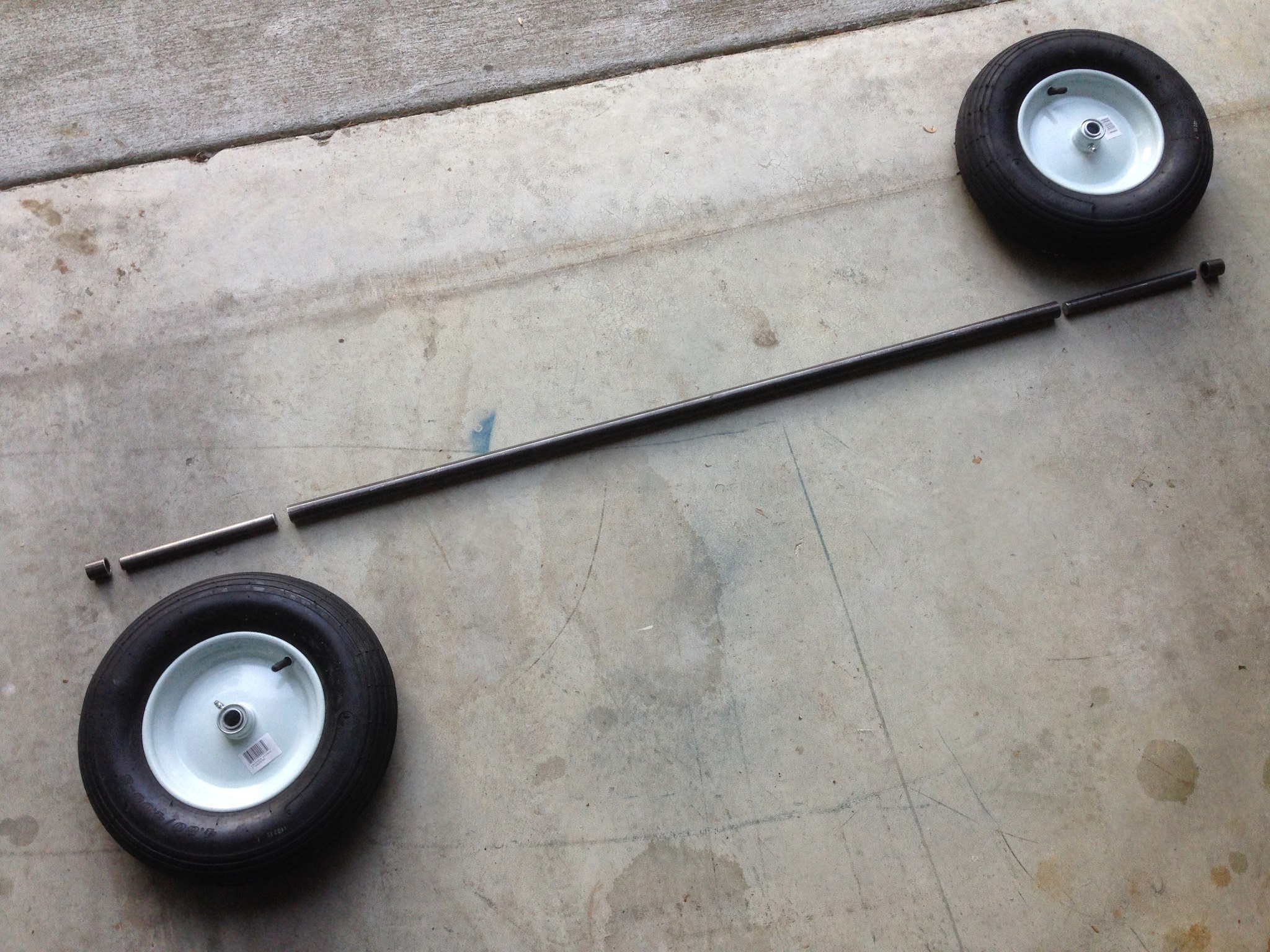
1" x .120 chromoly steel axle tube (45" long) and 3/4" OD chromoly axle stud rods (8" long). This is 10 times stronger and a few pounds heavier than the OEM solid 1" 6061 T6 axle. Ordinary 16" wheelbarrow wheels have been OEM since 1981 or so. But, instead of the OEM 3/16" thick plastic bushings for hub bearings, these have 3/4" bore ball bearings. |

Dry fit of the main landing gear. Still have to drill all the various holes for attaching fuselage brackets, wing strut tangs, and control stick items.
|

Detail shot showing a 1" long piece of axle tubing to be used as the wheel's entrapment. The wing strut tangs and bolt will hold it in place.
|

May 11, 2014
How to add band brakes to a standard wheelbarrow wheel (4.80/4.00-8 tire). Shown further below are go-kart type band brakes. I got a "kit" that contained the unmilled 4" diameter drum, a matching steel band lined with brake material, and a cable anchoring pin. |

The 4" OD drum has a 2" ID hole surrounded by 8 bolt holes, one set of four being 5/16" dia. and the other four 3/8".
In order to get the drum perfectly centered on the wheel rim (which has a 3" wide centered hub that is 1 5/8" OD) I used 10 layers of cereal box cardboard cut into 1" wide strips and simply wrapped a strip around the hub, marked the overlap point, cut it there, and then taped the ends together. Rinse and repeat until the brake drum snuggly fits the stacked up layers of cardboard, as shown below. |
 |
Marking the 5/16" bolt hole pattern on the wheel with a pencil.
|
 |
With holes marked, tap a set punch in the center of each circle.
|

A small drill press will not accommodate the 16" diameter of the tire, so I had to resort to drilling the holes with a hand drill.
These are 1/8" pilot holes. The drill doesn't have to be perfectly vertically "level" when drilling the top half of the wheel rim, but then you need to position the drill as vertically level as possible to drill the rest of the way through the bottom half of the wheel rim. To do that, I used a dual bubble level app on my iPhone. I held the phone on a lip on the drill's battery and tilted the drill until the readings were as close to 0 and 90 degrees as possible. I then began drilling at very low speed until the bit was seated, then proceeded with firmer down pressure and at a faster speed. |
 |
Next, drill to final size using a 5/16" bit.
|

Five washers stacked on 1.5" long 5/16" grade 5 bolts to space the drum 1/4" away from the wheel rim.
It's tricky to balance the drum and four bolts on the tips of your fingers and thumb, but this way was easier to insert the lowest bolt into the lowest hole in the wheel as the two parts were tilted vertical. |
 |
Final inside assembly.
|

Final outside assembly.
No lock or bearing washers needed under the nylock nut. Only about one thread protrudes from the nut after torquing it down. Too much torque and the thin metal of the wheel rim will start to crush. Since the wheel rim is convex, only a little bit of the nuts and washer stack touch the surface, so I'm not sure how this will behave under the force of braking. |

May 12, 2014
I made 1:1 scale templates of the bends for each fuselage brace on large sheets of drawing paper. This makes it a snap to get each pair of tubes bent EXACTLY the same amount. Bends were made with a "modified" 3/4" EMT conduit bender (around 5 1/2" radius). The modification was to file out the 15/16" diameter curved channel in the cast aluminum head with a 1/2" radius file to a smidge over 1". OK, but what happens if you over bend a tube? Well, take it to your friendly forked tree trunk, wedge it in the 'V' crevasse, firmly grip the tube, and pull on the it in the 'unbend' direction. Don't be too aggressive or too timid. The tube will flex and bend and spring back, so give it a little tug, remove, recheck against the template, and retry until just right. |

Drilling and attaching the center fuselage braces to the multi-junction axle brackets.
Due to the lowered wing TE, I made these braces 1 1/2" longer than OEM... 49 1/2" vs. 48". The bends shown here start 6" up vs. OEM's 4" in order to give the control stick more clearance. Bend angle = 32 degrees. The ONLY thing you have to watch out for is to get the second bend to be in the same plane as the first. Even though this was foremost in my mind, the tube must have twisted a couple of degrees without me knowing and I ended up with the second bend being "twisted" off-plane with the first. I succeeded in correcting the "twisted" bend by pinning one end to the floor by backing my small sports car on top of the tube (protected by a 2x6 block of wood). I then placed the free end of the tube on top of two stacked 2x6 blocks and stepped down on the bend with my full body weight a few times until it laid flat on the floor or reasonably so. |
 Due to the lack of repeatability in drilling every hole in exactly the same place as other holes drilled earlier (even if done on a drill press), you'll NEVER get new holes in new parts to line up perfectly. Therefore, you must use the existing holes in a bracket like this one as a guide for the bit. Drill one side, and then the other and then push the bit all the way both holes. Due to the lack of repeatability in drilling every hole in exactly the same place as other holes drilled earlier (even if done on a drill press), you'll NEVER get new holes in new parts to line up perfectly. Therefore, you must use the existing holes in a bracket like this one as a guide for the bit. Drill one side, and then the other and then push the bit all the way both holes. Center braces drilled and bolted to the multi-junction C-channel axle brackets. Center braces drilled and bolted to the multi-junction C-channel axle brackets. |

May 13, 2014
I incorrectly drilled the holes in the tops of the center braces for bolting to the boom, which I won't repeat for the rear tubes. What I did was drill the holes starting with the outside wall of the tube frist. Even though I carefully measured exactly 1/2" down from the top edge and on the center line, it was nowhere close to lining up with the holes in the boom. By 'nowhere close,' I'm talking 1/16" to 3/32" off axis. What I needed to do is buy a LONG shank bit that can pass through the boom and BOTH 1" tubes on either side, including any saddle spacers. Unfortunately, standard bits fall way short of this capability. To make the bolt pass through all three tubes, I had to wallow out the ill-drilled holes. I will fix this mistake by cutting 3/4" off the top ends of the brace tubes to get rid of the bad holes, buy a long shank 1/4" bit, and drill new holes, this time doing the inner wall first and then drilling through the outside wall by using the boom holes as a bit guide. Yes, the braces will be that much shorter, but I don't have any tubes to remake the braces and this is what is so nice about Weedhoppers... they're so forgiving about such dimensions due to their triangular construction. In my case, since this is being built from scratch, I'll let the holes in the existing (salvaged) front fuselage brace tubes, which attach to the engine mount angle brackets, to "float" to wherever they end up. |
 May 14, 2014: Another day, another fuselage brace. This time the rear set. May 14, 2014: Another day, another fuselage brace. This time the rear set.After bending the ends 14 degrees, I positioned the bottom of the C-channel axle brackets flat on the floor and then placed the tube in the channel flat against the floor... 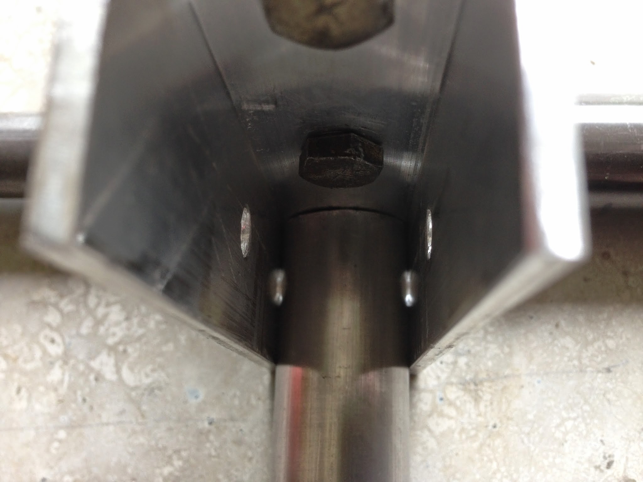 ... and all the way back against the back "wall" of the bracket. ... and all the way back against the back "wall" of the bracket. |
 Then I drilled it using the holes in the bracket as the bit guide. No need for a pilot hole first. Then I drilled it using the holes in the bracket as the bit guide. No need for a pilot hole first.Drill one side, then the other.  Then plunge the drill all the way through both holes. Remove the tube and deburr the holes. Then plunge the drill all the way through both holes. Remove the tube and deburr the holes. |
 To allow the tube to rotate upward in the bracket, cut a wedge off the top edge... like so. To allow the tube to rotate upward in the bracket, cut a wedge off the top edge... like so. To drill the other end for connection to the boom, first mark 1/2" below the edge on the center line. To drill the other end for connection to the boom, first mark 1/2" below the edge on the center line. |
 Then drill an 1/8" pilot hole in the inside wall only, then a 1/4" hole. Then drill an 1/8" pilot hole in the inside wall only, then a 1/4" hole. Next, with a long shank 1/4" bit placed through the holes in the boom, place any saddle spacers on the bit and then slip the tube's inside wall hole over the bit and begin drilling through the outside wall. Next, with a long shank 1/4" bit placed through the holes in the boom, place any saddle spacers on the bit and then slip the tube's inside wall hole over the bit and begin drilling through the outside wall.Remove the bit from all tubes and saddles, switch sides, and repeat for the the other fuselage tube. |
 Update: May 30... Well, almost. Better to incorporate the use of the Big Gator V-drill Guide... see 'Misc' page. |

May 14, 2014
I measured the distance between the top rear corners of each C-channel axle bracket to the aft end of the boom and only had a mere 1/8" difference... well within spec and tolerance range of no more than 1/4" frame alignment. Next on the list... nose strut, seat tubes, and gas tank support tubes. |

May 30, 2014
Fuselage progress. Seat tubes marked (center line and bends), measured, cut, drilled, polished, and mounted. Total weight at this point: 45 pounds. Warning! It is nearly impossible to get a conduit bender to make two bends at opposite ends of a tube that perfectly follow the tube's center line. There WILL be a few degrees of "twist." So the warning is: Do Not use the center line when drilling through holes on opposite ends of double-bent tubes. You will find one or the other to be "twisted" 10 to 20 degrees compared to the other! Instead, drill one end using the center line first, mount the tube in place, find the horizontal/vertical alignment with respect to the rest of the structure at the other end, and THEN drill the holes. I failed to do this for the seat tubes and ended up with holes for the U-bolts (see below) that were no where close to being perpendicular with the axle. I had to significantly wallow out the holes using an 1/8" dia round file in order to allow the U-bolts to move to an almost perpendicular orientation. |
 Nylon saddles for the seat tube/nose strut connection. Available from: Weedhopper USA Nylon saddles for the seat tube/nose strut connection. Available from: Weedhopper USA It's hard to see, on purpose, from this angle, but the U-bolts are slanted off-vertical due to the center-line bend warning above. It's hard to see, on purpose, from this angle, but the U-bolts are slanted off-vertical due to the center-line bend warning above.
The unused holes at the end are for attaching the seat-back/fuel tank support tubes. |

June 1, 2014
Measured, cut, bent, drilled, polished, and mounted the seat-back/tank tubes today. |

June 3, 2014
Installed the Phantom 11 gallon tank (vented at 5 gallons) and mounted the vertical stabilizer and horizontal stabilizer frames. Total weight thus far: 67 pounds. See "Tail" for v-stab and h-stab details. |

Another fine fit, although no matter how carefully I measured the center lines of the lower set of tank mounting holes, that good ol' hand tool intolerance snuck up and bit me again! This time on the lower right bolt hole in the 3/4" OD cross tube. It was a good 1/16" short. Again, round file to the rescue to elongate the hole so the bolt could "slide" over and thread into the threaded tank mounting insert.
I had never used the center mounting hole, but this time I am because the left-most insert (closest to you) pulled out in the crash. I heated the brass insert with a propane torch and pushed it back in to the tank. Hopefully some of the plastic oozed in around the insert's centered notch and locked it into place after cooling. |
 June 27, 2014: With seat, control horns added to tail group, and elevator control rod and yoke added, she weighs in at 90 pounds.
 The fuselage is nearly complete and weighs 102 pounds. Yep. The engine mount added about 10 pounds and 2 pounds came from the control stick, rudder cables, and restraint harness.
June 30 - July 4: 2014:
  Installation of the band brakes begins by locating and drilling a 3/8" hole for the brake band anchor bolt.Yes, every hole I drill gets deburred! |
  Laying out and cutting 3-1/4" x 1-3/4" x 1/8" aluminum reinforcement plates. |
  Outside view of installed reinforcement plates, one on either side of the C-channel multi-junction axle brackets, along with the 3/8" brake band anchor bolt, a cable seat L-bracket, spacers, and the 4" dia. brake band. The bolt has a 1/8" hole drilled thru its shank to allow the 3/32" cable to pass thru. |
  Inside view of the band brake installation without starboard wheel (left) and with port wheel (right). |
 Overall view of the completed control stick featuring a thumb-activated PTT (push-to-talk) switch on top of the rubber grip and an old-style Harley Davidson brake lever. 
Close up details of the Harley brake lever. A 1/2" dia. x 2" long steel pin replaces the 1" OEM pin that was used for anchoring a single brake cable. As you can see, the 2" pin has 1/8" holes drilled at each end for anchoring each wheel's band brake cable. This Harley lever is the 5/16" cable seat version. The seat is just a 1/4" recess in the lever base. I drilled it all the way through and then cut 3/8-24 threads into it. A short 3/8-24 bolt and lock washer hold a 2" x 1/2" x 3/16" bar on which the two cable seats are mounted. |
mister can you supply me with a dimensions for your desgin i need to try this
ReplyDeleteI have no dimensioned drawings. The best you can do is: https://www.weedhopperplans.com/weedhopper-single-place-model-40-plans
Delete